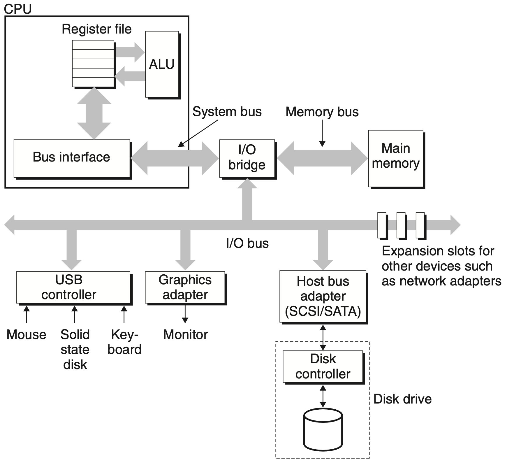
I/O Devices Diagram

I/O devices are connected to the CPU via I/O bus
Device Interaction
Port-Mapped I/O (PMIO)
I/O devices use a separate address space from main memory, either accomplished by an extra I/O pin on the CPU, or an entire bus dedicated to I/O
Uses explicit CPU instructions to perform I/O in/out
Such instructions are privileged and can be used only by the OS
Memory-Mapped I/O (MMIO)
I/O devices use the same address space as main memory
The memory and registers of the I/O device are mapped to address values, so a memory address may refer to either a portion of RAM or to memory and registers of the device
Uses the same CPU instructions to access both RAM and devices mov
This memory region is managed by the OS and cannot be accessed directly by user programs
Memory Mapped Registers
OS interacts with the device controller using device registers:
- Status register indicates the current status of the device
- Command register used to indicate the command to perform
- Data register stores data for reading and writing
There can be more registers: control register, error register, etc.
Data Transfer Mechanisms
Programmed I/O (PIO)
Each data item transfer is initiated by an instruction in the program, involving the CPU for every transaction
Polling
- Issue read/write command to I/O device
- Repeatedly check (poll) status register until the device is ready
- Perform read/write request between the device and RAM
- If there is more data, repeat with step 1
Inefficient because it spends a lot of time polling and moving data, waisting CPU resources
Interrupt-driven
- Issue read/write command to I/O device
- On interrupt, perform read/write request between the device and RAM
- If there is more data, repeat with step 1
Inefficient because it spends a lot of time moving data, waisting CPU resources
Direct Memory Access (DMA)
CPU first initiates the transfer, then it does other operations while the transfer is in progress, and it finally receives an interrupt from the DMA controller (DMAC) when the operation is done
- Issue read/write command to I/O device using DMA
Example read request:
- CPU initiates read memory request by executing three store instructions to I/O device registers
- Sends a command word that tells the disk to initiate a read, along with other parameters such as whether to interrupt the CPU
- Indicates the logical block number that should be read
- Indicates the main memory address where the contents of the disk sector should be stored
- The disk controller receives the read command, translates the logical block number to a sector address, reads the contents of the sector, and transfers the contents directly to main memory, without using the CPU
- The disk controller notifies the CPU by sending an interrupt signal to the CPU
Virtual Memory
The difficulties in having DMA in a virtual memory system arise because pages have both a physical and a virtual address
Network I/O
Write about network I/OTODO
References
- Computer Systems A Programmer’s Perspective, Global Edition (3rd ed). Randal E. Bryant, David R. O’Hallaron
- [CS61C FA20] Lecture 31.1 - I/O: I/O Devices - YouTube
- Direct memory access - Wikipedia
- Memory-mapped I/O and port-mapped I/O - Wikipedia
- Computer Organization and Design RISC-V Edition The Hardware Software Interface (2nd ed). David A. Patterson, John L. Hennessy
- Programmed input–output - Wikipedia
- I/O Techniques - Overview
- Operating Systems Three Easy Pieces. Remzi H Arpaci-Dusseau, Andrea C Arpaci-Dusseau
- Lec18 UNIX Operating System Calls Via x86 Traps - YouTube